IPC Blinking Dual Core Debugging
- Connectez-vous ou inscrivez-vous pour publier un commentaire
Source code can be downloaded from IPC_Blinking_DualDebug
Description
This simple demo shows communication between M4 and M0 cores. Two flags are used: first for commands from M4 to M0 and second for responses from M0 to M4. They both are located in shared memory. Inactive flags have zero value. So, when flag becomes non-zero, this means that command or response is received.
Algorithm
Algorithm for simple communication:
From M4 to M0:
- Set command flag.
- Wait for response flag becomes non-zero.
- Clear response flag.
- From M0 to M4:
- Wait for command flag becomes non-zero.
- Clear command flag.
- Set response flag.
- Execution
To run this projects you need:
- Open IPC_DualDebug_M4 project and build M4 program.
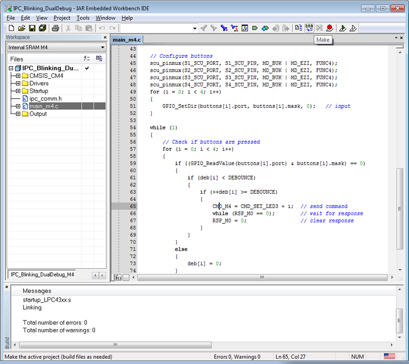
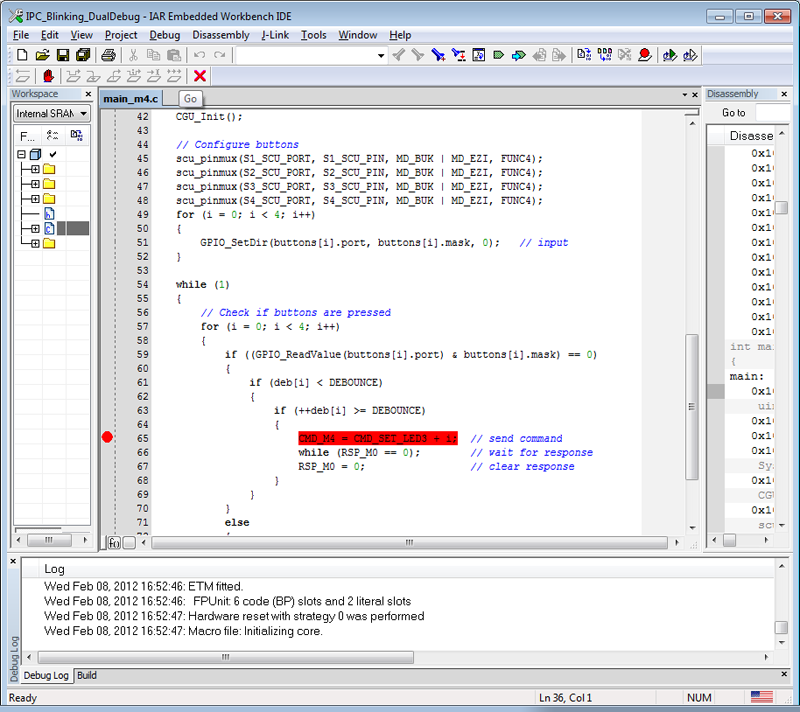
- Add a breakpoint to line 65 of main_4m.c source file, start debugging and run M4 program.
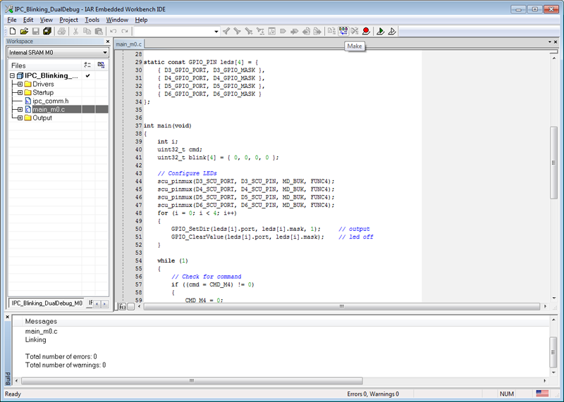
- Run second instance of IAR EWB, open IPC_DualDebug_M0 project and build M0 program.
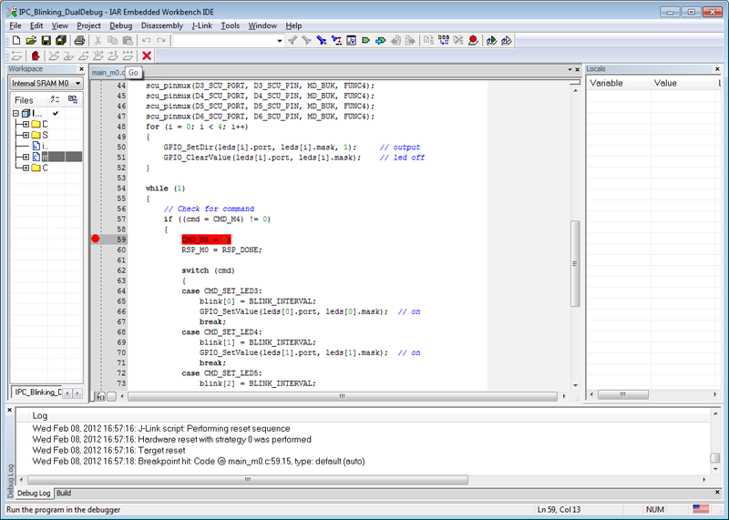
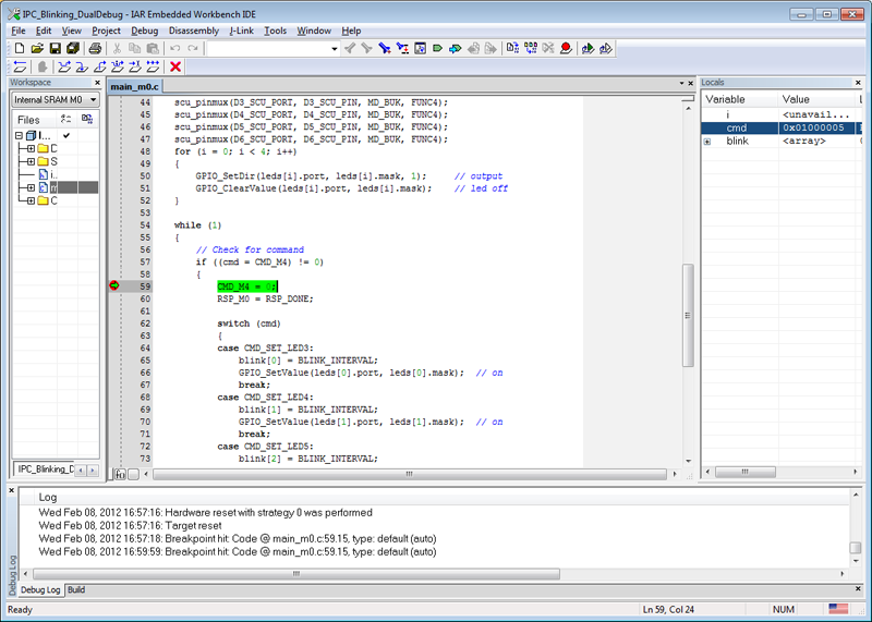
- Add a breakpoint to line 59 of main_0m.c source file, start debugging and run M0 program.
- Press any button on the board and M4 program will stop in breakpoint.
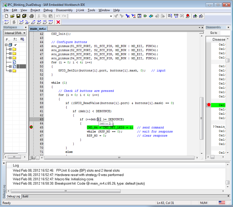
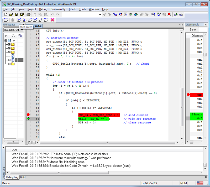
- Send command to M0 by running or stepping M4 program.
- M0 program will receive command and stop in debugger.
Anglais
